3. Requirements of HLL and application synthesis
HLL requirements
Memory classes (sections)
contain various types of objects required in the program
Control transfer
subroutine calls and returns, argument passing, local variables
Operations on data
arithmetic (+, -, *, /)
logic (~, &, |, ^)
data access - pointers/references, array indexing
Loops and conditional ops
for(), while(), do{} while()
if() else, switch ()
Program, task, thread
Program - static notation of an algorithm and data used by it
Task/process - a running instance of a program in a multitasking system
task has its own, private memory, not accessible by other tasks
many tasks may be running in a multitasking system
in a single-threading system task == thread
Thread - a running instance within a task/process
threads shared task's memory, thread's memory is not protected against other threads' access
In a single-tasking and single-threading system
program == task == thread
Memory classes
Code (text)
Static, present during the whole time of program execution
Fixed size
Read only
May contain:
- Program instructions
- Constants - address tables (for switch statements), literals (constant data values)
Static data
Same lifetime as the program
Fixed size
Can be divided into:
- Constants - read only (.rodata)
- Initialized var's - read/write, fixed init values (.data)
- Non-initialized var's - initial values must be set by program (.bss - Block Started by Symbol)
A thread may have its own static data besides task's static data
Dynamic automatic data
Procedure arguments and local variables
Created and destroyed during execution - variable size
Destroyed in reverse order with respect to creation
Implemented using stack - explains the reverse order
Every thread has its own stack
Dynamic controlled data
Created and destroyed explicitly by the programmer (malloc/free ,new/dispose)
Lifetime set by programmer, not related to procedure calling
Order of destruction unrelated to order of creation
Implemented using heap
Memory section in a multithreaded task
Text, static and heap sections shared between threads
A thread has its own
- Stack - obligatory
- Static Data - optional. Initialized (TDATA) or non-initialized (TBSS)
Thread-specific sections are created during thread creation
Application program address map
Four main areas - code, static, stack, heap
Typically heap grows upwards, stack downwards
Addresses close to zero are not used
so that null pointer dereferencing may be easily detected
Huge empty areas are present in the address space
Address space is NOT equivalent to memory
In g.p. computers with full mem management, running multitasking OS, address values are decided by the OS
In microcontrollers, the addresses of sections are partially fixed - enforced by the placement of memories in the address space
Symbolic representation of instructions
Instructions are stored as binary words in computer's memory
The binary representation of instructions is called machine language
Instruction binary image contains operation code and specification of arguments (encoded with 0's and 1's)
The machine instructions may be expressed symbolically in human-readable form - assembly language
Processors with different programming models have different assembly languages
Instruction notation - instr. name + argument specification
PC - Program counter
Register holding the address of the next instruction to be executed
During exec of instr. PC contains address of nextPC
PC always points to code section
Incremented during instruction fetch
During jump instruction PC is loaded with a new value pointing to the new sequent of instructions (non-sequential control flow)
PC is necessary in every von Neumann machine
Procedures - calls and returns
At the end of procedure, execution control must be passed by to the caller
Calling using CALL (jump and store trace)
Store the address of the next instruction following jump, then jump
Calling using RETURN
RETURN jumps to the address previously stored by CALL as a trace address
Stack
Data structure used for passing the control between program subroutines
Stores
- Call arguments
- Return traces
- Local variables
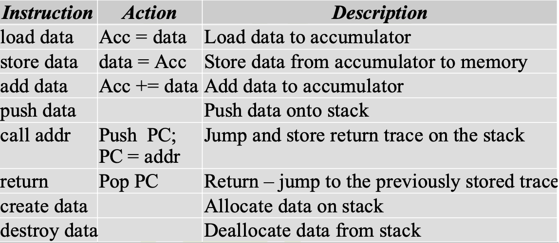
Simplest processor model
Registers:
- PC - Program Counter
- Single data register accumulator (Acc)
Stack with an unspecified implementation
At assembly language level, data specified by name or value
Instructions
Stack frame
Stack contains data related to all active procedures
Every procedure directly references only a small fragment of the stack, containing its own data, near the current top of stack
When the procedure starts execution, its arguments and return trace are present on the stack
Data structure present on the stack at the start of the procedure is called activation record
Procedure creates its local variables
Activation record + local variables = stack frame
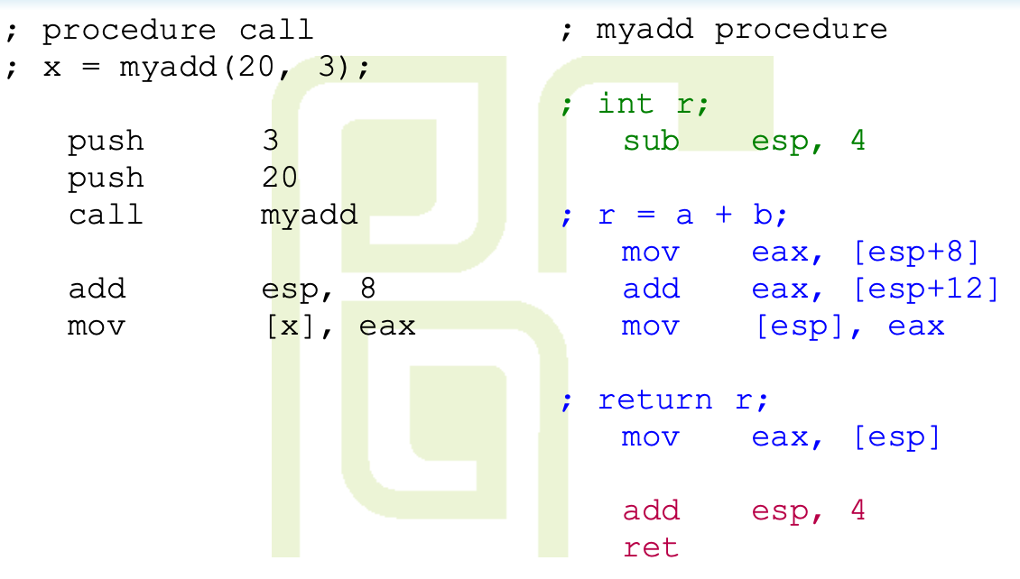
Stack frame addressing
Addresses of stack frame may be written as sums of SP and small ints
[SP + 12], [SP + 16]
But this technique is not convenient since SP changes values during execution of subroutine
After each PUSH, offsets from SP to all items increate by the size of pushed data (4 in 32-bit machine)
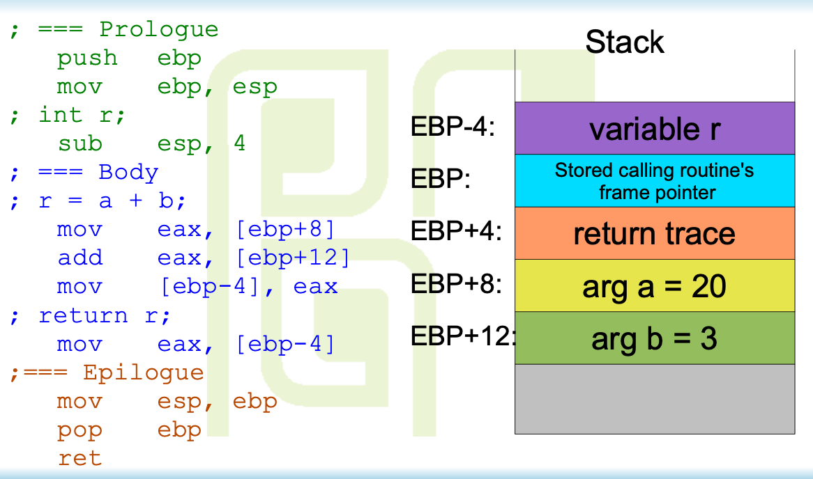
Frame pointer
To simplify stack frame processing, another register is introduces - Frame Pointer (FP)
FP points to the stack frame of a currently executing function
Frame pointer does not change during the execution of subroutine's body
- Every subroutine's body
- The subroutine may call another subroutine
- This effectively means that every routine must preserve the content of FP established by the caller
Operations on FP
First action inside a subroutine - storing FP on the stack and establishing a new value of FP
This value doesn't change during the exec of subroutine
Stack frame data is addressed relative to FP
Old value of FP must be restored before return
calling procedure FP is restored in function's epilog
CPU Model - x86 subset
Primary accumulator/value register - EAX
Stack pointer - ESP
Frame pointer - EBP
Program counter - EIP
Most instructions have two arguments
in standard notation, first argument is a destination
Register indirect with displacement addressing is available
data address obtained by adding the content of a register and signed displacement
asm notation [ESP + 4] means memory location with address being a sum of ESP and 4
x86 code, SP-relative addressing
x86 code, FP-relative addressing