7. Pipeline execution unit
5 pipeline stages
IF, RD, ALU, MEM, WB
IF and WB need only 1/2 of clock cycle - whole instruction takes 4 cycles
Harvard-Princeton architecture
Structure and operation
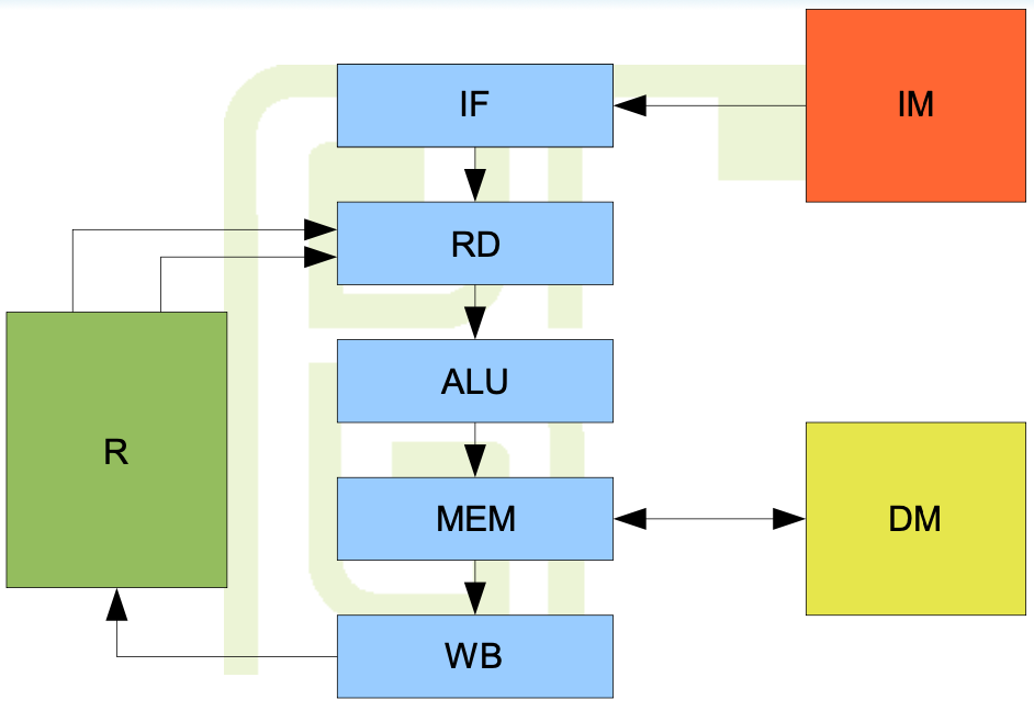
Every stage excluding WB has a D-type register at its output
PC and g.p. registers are updated in a half of the clock cycle
IF occurs in the second half of the cycle
WB works in the first half
Source arguments are ready in RD in the second half
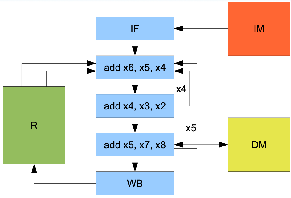
RAW Hazard
Consider the following sequence:
	add x4, x3, x2
	add x6, x5, x4
Problem - what value of x4 will be read by the second instruction?
This problem is called Read-After-Write Hazard
It is necessary to introduce some mechanisms to make the processor's behavior deterministic
Solution 1 - administrative method
The result of above code example is described in documentation as 'undefined'
The programmer is not allowed to use such instruction sequence
Programmer must write many empty instructions in program
	add x4, x5, x6
	nop
	nop
	add x6, x5, x4
Solution 2 - pipeline slipping
Hazard detection - combinatorial circuit in RD stage compares source register numbers against destination registers in ALU and MEM stage
Slip - if at least one pair of numbers is matched, the instruction is suspended in RD stage
IF and RD stop
the remaining stages work normally, RD injects empty instruction into ALU
Program executes correctly without NOPs in binary code
technically they are generated internally by the processor
Instruction dependencies cause delays
Solution 3 - bypasses
The result of ALU operation is ready while the instruction is in ALU stage
value is generated while the next instruction is in RD
Bypasses are data buses leading from ALU and MEM to RD
they contain dest register numbers and result values
Read logic in RD
source register numbers are compared against number present on bypasses
Priorities - ALU bypass, MEM bypass, physical register
No need to provide bypass from WB
Bypasses remove RAW hazard without delays
Load-use penalty
Assume the processor equipped with bypasses
Consider following sequence
	lw x4, ...
	add x6, x5, x4
This time, the RAW hazard results from memory load instruction
Data read from memory is not available until MEM stage
bypass from ALU stage will NOT contain proper data
The problem is called Load-use penalty
This hazard cannot be eliminated without delays
Branch conditions in pipeline
The branch condition and branch target are evaluated in ALU stage during first half of a cycle
At that time, RD already contains the next instruction
Branch instruction may influence the fetch of the second instruction after the branch
the instruction fetched after the branch may be turned into NOP but it will consume time
Branch penalty in pipeline results from non-zero distance between ALU and IF
Reduction of branch penalty
Delayed branch - 'execute the next instruction following the branch and then branch'
Any instruction originally placed before the branch which does not influence the outcome of the branch may be moved to the place after the branch instruction
The place of instruction after the branch which will be executed regardless of the outcome of the branch is called delay slot
When the delay slot size is one instruction, the probability of filling it with some useful instruction is about 90%
Pipeline efficiency
Theoretical efficiency -one cycle per instruction
Delay sources:
- Internal - hazards removed in other ways than bypasses, memory loads, branches
- External to the pipeline - memory hierarchy accesses
Practical efficiency - ~1.2 cycles per instruction
Seeding the pipeline
When the frequency increases, the memory cannot complete access during single cycle
The complexity of some pipeline stages makes it impossible to increase the clock frequency
The solution - redesign pipeline and increase number of stages while reducing the stages' complexity
Long pipeline (over 6 stages) is called superpipeline
Superpipeline
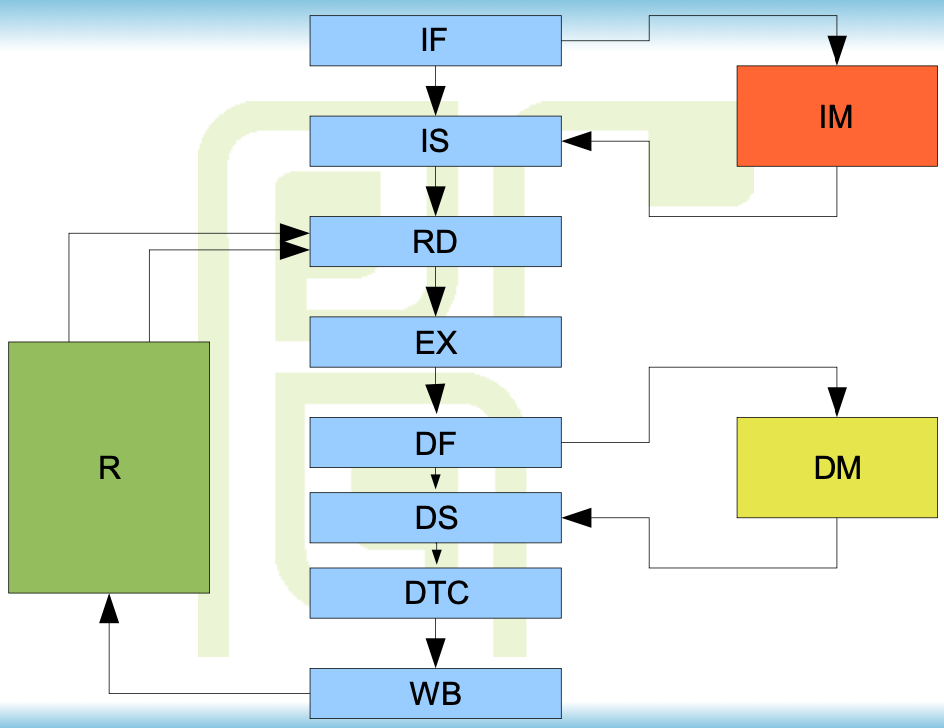
MIPS R4000
8 stages:
- IF - Instruction First - start of instruction fetch
- IS - Instruction Second - completion of instruction fetch
- RD - Read
- EX - Execute - ALU
- DF - Data First - start of data memory access
- DS - Data Second - second phase of memory access
- DTC- Data Tag Check - completion of data access
- WB - Write Back
Memory interface
Memory access divided into two phases
Memory is pipelined
access occurs in two clock cycles, which is naturally compatible with memory internal structure
two accesses are performed simultaneously
Synchronization and delays
Topology of the superpipeline is identical to pipeline
The increased number of stages results in greater distances between stages and bigger delays
More bypasses are needed
Load/use penalty and branch penalty are significantly bigger than in a short pipeline
Load-use penalty
With bypasses, the delay is equal to 3 cycles
not that critical
Memory references
reloading many registers in subroutine's prologue and epilogue
registers are accessed several instructions after load, masking the delay
references to data structures in memory - data frequently needed immediately after load - may cause significant delays
Branch penalty
Delay slot size is bigger than in short pipelines (2 instead of 1)
Probability of filling the delay slot with two useful instructions is low ~20%
The branch delayed by two cycles is not a good solution
also incompatible with earlier implementations
In superpipelined processors without pipelined ancestors, delayed branches are not used
The proper method of reducing the branch penalty in there architectures is branch prediction
Efficiency
Bigger and more frequent delays cause higher CPI ~1.5
But it is partially compensated by higher clock frequency
Net gain is around 50% in stages 5-8
Pipelined implementation of CISC
Due to incompatibility of CISC and pipelined architectures, there is no 'clean' implementation of CISC pipeline
Pipeline requirements not met by CISC
- Sequence of operations for all instructions is fixed
- Instructions have fixed length ! and simple formats
- Every instruction causes at most one data memory reference
- The instruction has at most one destination argument
Possible implementation
Enhanced, complex pipeline capable of executing CISC instructions
Processor divided into two parts:
- Unit fetching CISC instructions and converting them to sequences of RISC primitives
- Pipelined RISC execution unit
Problems
This implementation makes the beginning of a pipeline take multiple clock cycles (fetching, decoding, etc.)
Efficiency - CPI ~2
Frequent stalls and delays
Transcoder
Fetches CISC instructions and translates them into sequences of RISC-like instructions
For simple CISC instructions, 1 to 1 translation may be possible
Slightly more complex instructions converted to 2-4 RISC operations
The most complex instructions are implemented as calls to RISC routines placed in ROM inside the processor