Chapter 2
Basic Microcomputer
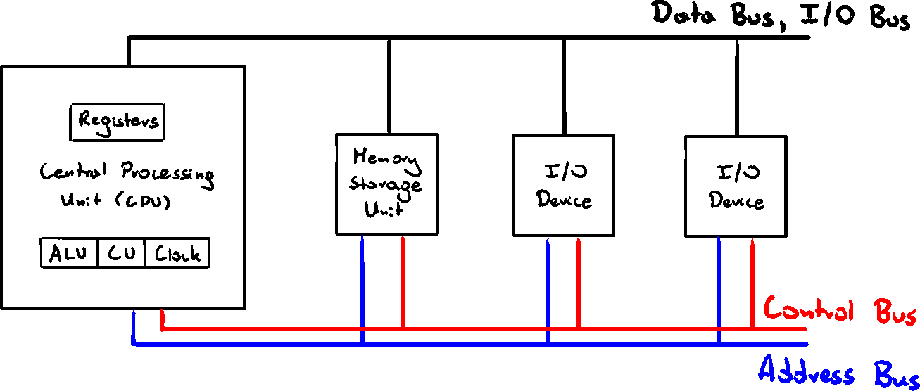
CPU
Handles calculations and logical operations
- Arithmetic Logic Unit (ALU) - performs arith. operations (
) - Control Unit (CU) - manages sequence of steps (instructions)
- Clock - synchronizes operations of CPU with other components
- Registers - internal CPU storage used for intermediate results
Memory Storage Unit
Holds data and instructions of a running program
Receives data requests from CPU and pulls that data from Random Access Memory (RAM) to CPU, and back
All processing of data takes place in CPU, so it has to be copied there
Data/instructions can be copied individually or in chunks
Bus
Parallel transfer path used to move data. We differentiate 4 types:
- Data - transfers data between CPU and memory
- I/O - transfers data between CPU and I/O devices
- Control - uses binary signals to synchronize actions of all devices
- Address - holds address of instructions and data when CPU is performing data transfer
Clock
Synchronizes CPU and system bus by an internal, constant-rate pulses
Unit of time - "machine cycle/clock cycle"

Machine instructions require at least one cycle, sometimes over 50 to complete
Instructions with memory access often have empty clock cycles - wait cycles - due to differences of speeds of components
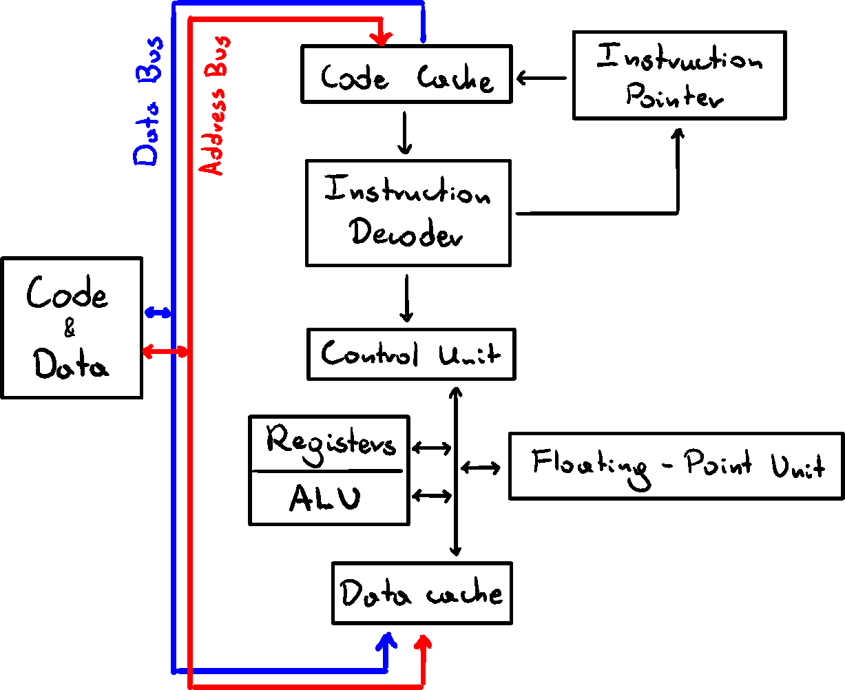
Instruction Execution Cycle
Each instruction has a sequence of steps to execute
Assuming Instruction Pointer (IP) register holds the instruction address
- CPU fetches the instruction from memory area - instruction queue
After that, increments IP - CPU decodes the intsruction from its binary bit pattern.
Binary Bit Pattern may show, that instruction requires operands (input values) - If operands are required, CPU fetches them from registers or memory
This may involve address calculations - CPU executes the instruction, using any available values, and updates the status flags - ie. ZERO, CARRY, OVERFLOW
- If the result is an operand, CPU stores the result in it
We usually simplify this into - Fetch, Decode, Execute
Reading From Memory
Reading memory is much slower than from register, because it involves 4 steps, each taking 1 clock cycle:
- Place address of the value in address bus
- Assert (change value of) processor RD (read) pin
- Wait 1 clock cycle for memory to respond
- Copy data from data bus to destination operand
To reduce delays, cache was created. It's a memory storage inside the CPu, which holds the repeatedly used values, so they can be accessed quicker.
If CPU finds data in cache - cache hit
If CPU fails to find data - cache miss
For x86 processor family, we have two types of cache
- L1 - attached right to the CPU (primary cache, faster)
- L2 - connected by high-speed bus (secondary cache, bigger)
Cache is faster than RAM, because it uses static RAM which doesn't have to be constantly refreshed like dynamic RAM, but is a lot more expensive
Loading and Executing a Program
Before running a program, it muse be places in memory by Program Loader, after which OS has to find the Program Entry Point and point it to CPU.
- OS finds program in current directory or PATH. If not - error
- OS gets the basic infor (size, location) and loads the program into available memory, allocating needed size. Loads program's info into the descriptor table.
- Begins execution from the entry point. Running program is called a process. Assigns process ID to track it.
- Process runs by inself. OS tracks it, and responds to data/access requests.
- When process finished, it's removed from memory.
32-bit x86 Processors
Modes of operation
- Protected - native state. Each process gets assigned separate memory 'segment' and can't access memory outside of it
- Virtual-8086 - way for protected mode to run real-address software (i.e. MS-DOS). Program crash or attempt to write system data won't affect other programs
- Real-address - early Intel proc. environment, with ability to switch to other modes. Useful for direct memory and hardware access. Not supported by new Windows
- System Management - allows OS to manage power, system security etc. Usually implemented by computer manufacturers
Basic Execution Environment
Basic x86 protected mode allows up to 4GB of linear address space.
Newer processors allow up to 64GB, using extended physical addressing
Real-address mode programs have only 1MB os space
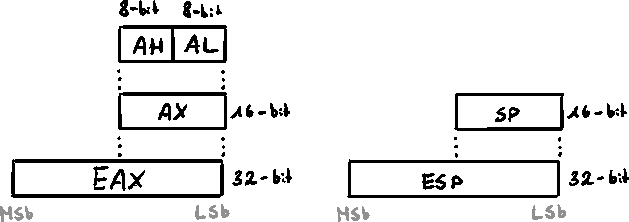
Basic registers
8 General-Purpose Registers
EAX, EBX, ECX, EDX, ESP, EBP, ESI, EDI
Used for arithmetic and data movement
We can reference parts of the register
Specialized Uses
- EAX - multiplication/division. Extended accumulator register
- ECX - loop counter
- ESP - Extended Stack Pointer
- EBP - references function parameters and variables on the stack
- ESI - memory transfer. Extended Source Index
- EDI - memory transfer. Extended Destination Index
Segment Registers
CS, SS, DS, ES, FS, GS
Hold pointers to segment descriptor tables in x86
Some point to stack, some to data
SS (Stack Segment) holds function variables and parameters
Instruction Pointer - EIP
Contains address of the next instruction to execute
Can be manipulated to branch to a new location
EFLAGS
Individual bits that control operation of CPU and reflect outcome of some operations
Control Flags
- Carry Flag (CF) - result of unsigned arithmetic operation, if the result is too large to fit into destination
- Overflow Flag (OF) - result of signed arithmeti operation, if the result is too small or too large to fit into destination
- Sign Flag (SF) - result is negative
- Zero Flag (ZF) - result is 0
- Auxillary Carry Flag (AC) - airthmetic operatioin caused carry from bit 3 to bit 4 in 8-bit operation
- Parity Flag (PF) - LSB contains even number of 1's
MMX Registers
8 64-bit, designed to improve performance of multimedia and communication applications
Support SIDM (Single Instruction-Multiple Data). Operate parallel on the data
XMM Registers
8 128-bit registers. Streaming SIDM extensions to the instruction set
Floating-Point Unit
Performs high-speed floating-point arithmetic. Integrated into CPU
- 8 FP 80-bit registers - ST(0), ST(1), ..., ST(7)
- 2 48-bit pointer registers
- FPU instruction pointer
- FPU data pointer
- 3 16-bit control registers
- Tag register
- Control register
- Status register
- Opcode register
Memory management
Real-address Mode
In real-address mode, only 1MB of memory can be accessed by an application - [0x00000 - 0xFFFFF]
Processor can run 1 program at a time, with interrupts to process requests from peripherals. Applications can access all memory, including system.
MS-DOS and old Windows
Protected Mode
Processor an run multiple programs at once, with cach process having up to 4GB of memory. Each program can access only its own memory, and is guarded against accessing other memory.
Windows and Linux
Virtual-8086
Computer runs in protected mode and creates V8086 machine with its own 1MB of memory and real-address 80x86 computer.
Multiple V8086 machines can be run at once.
64-bit x86-64 Processors
Backwards compatible with x86 instruction set
Addresses are 64-bit, allowing for
64-bit g.p. registers allow for 64-bit operands. 8 new g.p. registers
48-bit physical address space allows for up to 256TB of RAM
When running 64-bit mode, no support for 16-bit real mode and V8086.
64-bit Operation Modes
64-bit operation modes are called IA-32
- Compability (32-bit) mode - 16- and 32-bit programs can run without recompilation. No virtual DOS machines.
- 64-bite mode - Applications use 64-bit linear address space. Native for 64-bit Windows.
Basic 64-bit Execution Environment
Registers
- General-Purpose Registers
16 64-bit g.p. registers (in 32-bit mode, only 8 are available)
Subparts can be accessed. For 8-bit part, only the lowest 8 bits are available
| 8-bit | 16-bit | 32-bit | 64-bit |
|---|---|---|---|
| AL | AX | EAX | RAX |
| DIL | DI | EDI | RDI |
| BPL | BP | EBP | RBP |
| R8L | R8W | R8D | R8 |
- 8 Floating-Point 80-bit registers
- 64-bit RFLAGS (only lower 32 bits are used)
- 64-bit Instruction Pointer RIP
- 8 64-bit MMX
- 16 128-bit XMM
Components of a x86 Computer
Motherboard
Hosts CPU in a CPU socket, supporting processors (chipset), main memory slots (SIMM or DIMM), I/O connectors, power supply connectors, and expansion slots, BIOS (Basic Input-Output System)
Important support processors (Legacy)
- Floating-Point Unit - now incorporated into the CPU
- Clock generator
- Programmable Interrupt Controller (PIC) - handles external interrupts
- Programmable Internal Timer/Counter - updates system time and data
- Universal Serial Bus (USB) controller - handles USB data transfer
Historically, PCI connected CPU with other devices - hard drives, memory, video controller, sound & network cards
PCI Express is a two-way serial connection between devices, memory, and processor. It handles data in packets. High-speed data transfer.
Motherboard Chipset - collection of processor chips implemented to increase processing power, multimedia capabilities, and decrease power consumption
Memory
- Read-Only Memory (ROM) - permanently burned into chip. Non-erasable
- Erasable Programmable Read-Only Memory (EPROM) - erasable using UV light
- Dynamic RAM (DRAM) - main memory. Holds processes and data. Cheap but must be frequently refreshed to keep the data
- Static RAM (SRAM) - high-speed. Doesn't need refreshes, but expensive
- Video RAM (VRAM) - dual-ported. Gets written on one side and outputs simultanously on the other side
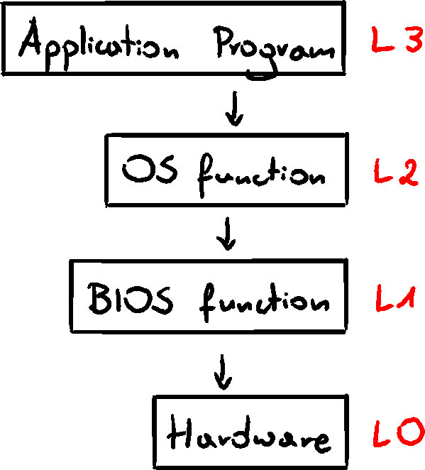
Input-Output Systems
I/O is extremely performance-heave
Applications frequently write/access drives, screen, audio, etc. but they shouldn't directly access those devices. They call functions provided by OS. I/O access has levels:
- High-level language functions
- OS - functions callable from library operating system API - Application Programming Interface. Provides high-level operations such as write, read, allocate...
- BIOS - collection of low-level subroutines that communicate directly with hardware devices. Installed by manufacturer, tailored to components. OS communicates with BIOS.
Device Drivers
Program allowing OS to directly communicate with hardware or BIOS
Handles OS requests to devices
Installed in one of two ways:
- Before hardware is attached
- After hardware is attached and identified
Example displaying character on screen
- Statement in application code calls HLL library
- Library function (L3) calls OS, passing a string pointer
- OS function (L2) loops to call BIOS with ASCII and color, and move to next position
- BIOS subroutine (L1) maps the ASCII to font and sends the character to hardware port with the video card
- Video controller card (L0) generates timed hardware signals to display
Assembly can work on and choose between all levels.
Decision for using which level is a trade-off between control and speed vs portability