Chapter 6
This chapter introduces boolean operations, uses for conditional jump and loop instructions, implementation of finite-state machine, and MASM built-in 32-bit logic structures.
A conditional branching is a technique used by programming langauges to allow for altering flow of control, based on decision making.
Boolean and Comparison Instructions
Chapter 1 introduced four basic operations in boolean algebra - AND, OR, XOR, and NOT. These operations can be carried out at the binary bit level, using assembly instructions. They are important at the boolean expression level, for example in IF statements.
The Intel instruction set contains AND, OR, XOR, NOT, and TEST
CPU Status Flags
Boolean expressions affect Zero, Carry, Sign, Overflow, and Parity flags.
- Zero - set when result of an operation equals zero
- Carry - when an operation generates a carry out of the highest bit of the destination operand
- Sign - copy of the MSb of the destination operand. Set = negative
- Overflow - set when isntruction generates a result that is outside the signed range of the destination operand
- Parity - set when an instruction generates an even number of 1 bits in the LSB of the destination operand
Boolean Instructions
AND Instruction
AND instruction performs a boolean (bitwise) AND operation beetween each pair of matching bits in two operands and places the result in the destination operand
The immediate operands cannot be larger than 32 bits.
The result for each bit
| 0 | 0 | 0 |
| 0 | 1 | 0 |
| 1 | 0 | 0 |
| 1 | 1 | 1 |
AND operation is usefult for clearing 1 or more bits without affecting other bits. This technique is called masking. To clear bits 0 and 3:
and AL, 11110110b
Flags
AND instruction always clears Overflow and Carry flags.
It modifies Sign, Zero, and Parity flags based on the result
Converting Characters to Upper case
Using AND one can easily translate a letter from lowercase to uppercase.
ASCII is made in such a way, that lower and uppercase letters are exactly 32 bits (20h) apart:
	0 1 1 0 0 0 0 1 = 61h ('a')
	0 1 0 0 0 0 0 1 = 41h ('A')
By clearing the bit 5 (AND cx, 11011111b) we can convert a letter to the uppercase
OR Instruction
OR performs a boolean OR between each pair of mathing bits in operands and places the result in the destination operand
Operands can be up to 64 bits, and equal size
The result for each bit:
| 0 | 0 | 0 |
| 0 | 1 | 1 |
| 1 | 0 | 1 |
| 1 | 1 | 1 |
OR instruction is useful for setting a specific bit without affecting other ones. To set the bit 2:
or AL, 00000010b
Flags
OR always clears Carry and Overflow.
It modifies Sign, Zero, Parity according to the result.
One can obtain certain information about the value by OR'ing itself
OR al, al. The values of Zero and Sign flags indicate the following:
| ZERO | SIGN | Value is ... |
|---|---|---|
| 0 | 0 | > 0 |
| 1 | 0 | = 0 |
| 0 | 1 | < 0 |
XOR Instruction
XOR performs an exclusive-OR operation on each pair of matching bits in two operands and stores the result in the destination operand
The result for each bit:
| 0 | 0 | 0 |
| 0 | 1 | 1 |
| 1 | 0 | 1 |
| 1 | 1 | 0 |
Checking the Parity Flag
Parity checking is a function performed on a binary number that counts the number of 1 bits contained in the number. The result is either even or odd parity. in x86 processors, parity flag is set when LSB of the result has even parity. When the result has odd parity, the flag is cleared.
16-bit Parity
To check the parity of a 16-bit integer, XOR between upper and lower bytes can be used
	mov ax, 64C1h
	xor ah, al
32-bit Parity
To calculate 32-bit values, a XOR between lowest bytes can be performed
XOR in Encryption
XOR has a very interesting property, useful in basic encryption. When a value is XOR'ed by some key value twice, it reverts back to it's original self $$ ((X \oplus Y) \oplus Y) = X $$
This allows us to create a basic single-key encryption. If we take a plain text, and use a key to XOR every character of this text, we get a cipher text, that can be only decrypted if somebody obtains the exact key it was encrypted with.
NOT Instruction
NOT instruction inverts all bits in an operand. The result is called one's complement. Permitted operand types:
No flags are affected by NOT instruction
TEST Instruction
TEST instruction performs an implied AND operation between two operands, setting Sign, Zero, and Parity based on the result. Only difference from AND is that TEST doesn't modify the destination operand.
Testing Multiple Bits
TEST instruction can check several bits at once. To check whether bit 0 or bit 3 are set:
test al, 00001001b
The value 00001001 is called a bit mask.
Flags
TEST always clears Overflow and Carry flags.
It modifies Sign, Zero, and Parity falgs, in the same way as the AND instruction
Bit-Mapped Sets
Some applications manipulate sets of items selected from a limited-sized universal sets. Example of that is bits representing set membership/access level. A bit-mapped set introduces one-to-one correspondence between a sequence of binary bits and set membership.
It's a simpler alternative to Java HashSet, by using bit vector (ordered sequence of bits) to map the bits in binary number to an array of objects.
The following binary number indicates a given set:
By using AND on the position, it's easy to check for set membership
	mov eax, SetX
	mov eax, 10000b    ; is element[4] a member of SetX?
If the AND clears Zero flag, the element[4] is a member of SetX
Set Complement
To generate a complement of a set, NOT instruction can be used
	mov eax, SetX
	not eax
Set Intersection
AND instruction procudes a bit vector that represents intersection of two sets
	mov eax, SetX
	and eax, SetY
Set Union
OR instruction outputs a bit map that represents the union of two sets
	mov eax, SetX
	or eax, SetY
CMP Instruction
Besides bitwise instructions, comparision is most common in logical expressions.
In x86 assembly, CMP instruction can be used to compare integers. It works for integers and character codes (as they are also integers).
Floating-point values require specialized comparison instructions.
CMP instruction performes an implied subtractoion of source operand from the destination operand. Neither of them is modified
Flags
The CMP instruction changes Overflow, Sign, Zero, Carry, Auxiliary Carry, and Parity flags according to the value of the subtraction result
Possible relations between operands:
CMP results |
ZERO | CARRY | Difference of flags |
|---|---|---|---|
| Destination < Source | 0 | 1 | |
| Destination > Source | 0 | 0 | |
| Destination = Source | 1 | 0 |
CMP is very important for conditional logic structures. Combination of CMP and a conditional jump instruction is equal to an IF statement
Setting and Clearing Individual CPU Flags
To set Zero flag, TEST or AND an operand with 0, to clear - OR with 1
	test al, 0    ; set Zero flag
	and  al, 0    ; set Zero flag
	or   al, 1    ; clear Zero flag
TEST doesn't modify the operand, whereas AND does.
To set Sign flag, OR the highest bit with 1, to clear - AND MSb with 0
	or  al, 80h    ; set Sign flag
	and al, 7Fh    ; clear Sign flag
To set Carry flag, STC instruction must be used. To clear - CLC
	stc    ; set Carry flag
	clc    ; clear Carry flag
To set Overflow flag, add two positive values that produce a negative sum. To clear - OR an operand with 0
	mov al, 7Fh    ; AL = +127
	inc al         ; AL = -128, OF = 1
	or  eax, 0     ; clear Overflow flag
Boolean Instructions in 64-bit Mode
64-bit instructions work almost exactly the same as they do in 32-bit mode. If an operation is performed with an immediate that is smaller than the destination, all of the bits are affected
.data
	allOnes QWORD 0FFFFFFFFFFFFFFFFh
.code
	mov rax, allOnes
	and rax, 8080h    ; RAX = 0000000000008080h
But, when the operand is a 32-bit constant or register, only lower 32 bits are affected
	mov rax, allOnes
	and rax, 80808080h   ; RAX = FFFFFFFF80808080h
Conditional Jumps
Conditional Structures
x86 instruction set doesn't have a block-oriented conditional instructions like IF, ELSE, and ENDIF, but using a combination of comparisions and jumps, similar conditional structures can be implemented.
In conditional structure execution there are two steps:
- Modification of CPU status flags by an instruction such as
CMP - Conditional jump instruction testing flags and branching to a new address
Examples
The CMP instruction compares EAX to zero. The JZ (jump if zero) instruction jumps to label L1 is the ZF was set by CMP
	cmp eax, 0
	jz L1             ; jump if ZF = 1
	...
L1:
	...
The AND instruction performs a bitwise AND on DL register, affecting ZF then JNZ (jump if not zero) instruction jumps if the ZF is clear
	and dl, 10110000b
	jnz L2            ; jump if ZF = 0
	...
L2:
	...
JCOND Instruction
A conditional jump instruction branches to a destination label when status flag condition is true. Otherwise, execution goes to the instruction following the jump instruction.
The syntax:
JC- jump if carryJNC- jump if not carryJZ- jump if zeroJNZ- jump if not carry
CPU status flags are usually set by arithmetic, comparision, and boolean instruction. Conditional jump instructions evaluate flags, using them to determine whether the jump should be taken
Using CMP Instruction
To jump to label L1 when EAX equals 5, a CMP should be performed on EAX register and then JE (jump if equal)
	cmp eax, 5
	je L1
To jump if EAX is less than 6 - JL (jump if less)
	mov ax, 5
	cmp ax, 6
	jl L1
Types of Conditional Jump Instructions
x86 instruction set has a large number of conditioanl jump instructions. They perform actions based on values of CPU flags or comparision between signed/unsigned integers
The conditional jump instructions can be divided into four groups:
- Based on specific flag values
- Based on equality between operands of the value of RCX, ECX, or CX
- Based on comparisons of unsigned operands
- Based on comparisons of signed operands
Jumps Based on Flag Values
| Mnemonic | Description | Flags/Registers |
|---|---|---|
JZ |
jump if zero | |
JNZ |
jump if not zero | |
JC |
jump if carry | |
JNC |
jump if not carry | |
JO |
jump if overflow | |
JNO |
jump if not overflow | |
JS |
jump if signed | |
JNS |
jump if not signed | |
JP |
jump if parity (even) | |
JNP |
jump if not parity (odd) |
Equality Comparisons
The jump instructions are based on evaluating equality. In some cases, two operands are compared, in some - value of CX, ECX, or RCX.
In the table, CMP instruction
| Mnemonic | Description |
|---|---|
JNE |
jump if not equal ( |
JCXZ |
jump if |
JECXZ |
jump if |
JRCXZ |
jump if |
Technically, JE is equal to JZ, and JNE to JNZ, but it's best to use mnemonic that best indicates the intention to either compare two operands or examine the specific flag
Unsigned Comparisons
Same as above,
| Mnemonic | Description |
|---|---|
JA |
jump if above ( |
JNBE |
jump if not below or equal (same as JA) |
JAE |
jump if above or equal ( |
JNB |
jump if not below (same as JAE) |
JB |
jump if below ( |
JNAE |
jump if not above or equal (same as JB) |
JBE |
jump if below or equal ( |
JNA |
jump if not above (same as JBE) |
Signed Comparisions
The below list makes sense only for comparision of signed integers. In the below example, JA doesn't jump because unsigned 7Fh is smalled than unsigned 80h, but for a signed comparision it jumps as
	mov al, 7Fh    ; -127
	cmp al, 80h    ; +128
	ja  isAbove    ; not taken
	jg  isGreater  ; taken
| Mnemonic | Description |
|---|---|
JG |
jump if greater ( |
JNLE |
jump if not less than or equal (same as JG) |
JGE |
jump if greater than or equal ( |
JNL |
jump if not less (same as JGE) |
JL |
jump if less ( |
JNGE |
jump if not greater than or equal (same as JL) |
JLE |
jump if less than or equal ( |
JNG |
jump if not greater (same as JLE) |
Conditional Loop Instructions
LOOPinstructions do not affect any status flags
LOOPZ and LOOPE Instructions
The LOOPZ (loop if zero) instruction works exactly like LOOP instruction, with one additional condition - ZF must be set in order for control to transfer to the destination label. The syntax: $$ \text{LOOPZ destination} $$
The LOOPE (loop if equal) is equal to LOOPZ, sharing the same opcode! Their execution is as follows:
	ECX = ECX - 1
	if ECX > 0 and ZF = 1, jump to dest
Otherwise, no jump occurs and control goes past the jump instruction.
LOOPZ and LOOPE don't affect any status flags (this means that the decrementation of ECX doesn't affect flags either!!!).
In 32-bit mode, ECX is used as the loop counter, in 64-bit mode - RCX.
LOOPNZ and LOOPNE Instructions
LOOPNZ (loop if not zero) and LOOPNE (loop if not equal) are counterparts of the previous instructions. The loop continues while the unsigned value of ECX is greater than zero (after being decremented) and the ZF is clear. The execution steps:
	ECX = ECX - 1
	if ECX > 0 and ZF = 0, jump to dest
Example
The below code checks each number in an array until a nonnegative number is found (sign bit is clear).
.data
	array SWORD -3, -6, -1, -10, 10, 30, 40, 4
.code
	mov esi, OFFSET array
	mov ecx, LENGTHOF array
L1:
	test WORD PTR [esi], 8000h   ; test sign bit
	pushfd                       ; push flags onto stack
	add esi, TYPE array          ; move to the next value
	popfd                        ; pop flags from the stack
	loopnz                       ; continue loop if SF = 1
	jnz quit                     ; none found
	sub esi, TYPE array          ; ESI points to the value

quit:
Notice lines 8 and 10, where the flags are pushed and poped to and from the stack. This is needed as the ADD instruction in line 9 (moving into the next index) will cause the flags to be updated, removing TEST flags.
The SUB on line 13 is caused by the fact that the code always moves to the next number before checking the loop, so if that value was TYPE is required to come back to the proper value offset.
Conditional Structures
Conditional structure is defined as one or more conditional expressions that trigger a choice between different logical branches. Each branch causes a different sequence of instruction to execute.
Block-Structure IF Statement
An IF structure contains a boolean expression followed by two lists of statements - one performed when the expression is true, the other when it's false.
if (boolean-expr)
	list_if_true
else
	list_if_false
The ELSE statement is optional.
In assembly, conditional stuctures have to be coded in steps:
- evaluate the boolean expression to affect CPU flags
- construct series of jumps that transfer control based on CPU flags
Example
An example, simple if-statement in C++
if (op1 == op2)
{
	X = 1;
	Y = 2;
}
To translate it into assembly, CMP with conditional jumps has to be used. To use CMP, one of the op1/op2 has to be moved to the register before being used. The following code is the most efficient, allowing code to 'fall through' the two MOV instructions on the true condition
	mov eax, op1
	cmp eax, op2
	jne L1
	mov X, 1
	mov Y, 2
L1:
Despite the C++ code containing equality == operator, the assembly code uses JNE (jump if not equal) instruction. This is caused by the fact that this creates the most simple, readable code. If JE were used, the code becomes slightly more complicated
	mov eax, op1
	cmp eax, op2
	je L1
	jmp L2
L1: mov X, 1
	mov Y, 2
L2:
Based on this example, it can be understood that one conditional structure can be translated into assembly in multiple ways (using different jump conditionals, etc.). Any further examples will show the best possible code, hypothetically created by a compiler.
Another example, containing two branches:
if op1 > op2
	call Routine1
else
	call Routine2
endif
Assuming that op1 and op2 are signed doublewords
	mov eax, op1
	cmp eax, op2
	jg A1
	call Routine2
	jmp A2
A1: call Routine1
A2: ...
White Box Testing
Complex conditional statements usually have multiple execution paths and are hard to debug by just reading the code. White box testing is a technique used to understand and verify subroutine's inputs and corresponding outputs, by manually tracing the source code and veryfing the execution path and outputs produced by the subroutine. It requires a full access to the source code.
For the example nested-IF statement:
if op1 == op2
	if X > Y
		call Routine1
	else
		call Routine2
	endif
else
	call Routine3
endif
The following is a possible translation to assembly. The initial condition op1 == op2 is reversed creating an easier to read code.
	mov eax, op1
	cmp eax, op2    ; op1 == op2?
	jne L2          ; no -> call Routine3

; inner IF statement
	mov eax, X
	cmp eax, Y      ; X > Y?
	jg L1           ; yes -> call Routine1
	call Routine2   ; no -> call Routine2
	jmp L3          ; exit
L1:
	call Routine1
	jmp L3
L2:
	call Routine3
L3:
A flow graph of the above code:
!Nested IF-Statement Graph.canvas
Compound Expressions
Logical AND Operator
A compound expressions consists of two or more subexpressions, joined by AND, OR or NOT. Assembly easily implements compound expressions containing AND operator. Considering the following pseudocode:
if (al > bl) AND (bl > cl)
	X = 1
endif
Short-Circuit Evaluation
The following is a straightforward implementation using short-circuit evaluation (AND), where the second expression is not evaluated if the first expression is false. This is typical for HLL:
	cmp al, bl
	ja L1
	jmp next
L1: cmp bl, cl
	ja L2
	jmp next
L2: mov X, 1     ; both true, X = 1
next:
We can reduce the code to five instructions by changing the initial JA into JBE:
	cmp al, bl
	jbe next
	cmp bl, cl
	jbe next
	mov X, 1      ; both are true
next:
Logical OR Operator
When a compound expressions are joined using OR operator, the overall is true if any of the subexpressions are true. Based on the following pseudocode:
if (al > bl) OR (bl > cl)
	X = 1
In the assembly code, if any of the CMP are evaluated to be true by conditional jumps, it immediately goes to executing the 'true' block
	cmp al, bl
	ja L1       ; if true, no need to check second expr
	cml bl, cl  ; previous was false, so check second expr
	jbe next    ; if also false, skip L1
L1: mov X, 1
next:
The same as previously, there are multiple ways to implement the compound expressions in assembly.
WHILE Loops
A while loop tests a condition before performing a block of statements. The loop is repeated as long as the conditions remain true.
The following C++ loop:
while (val1 < val2)
{
	val1++;
	val2--;
}
During assembly implementation, it's convenient to reverse the loop condition and jump to endwhile if the condition is true. This makes the code more readable
	mov eax, val1
beginWhile:
	cmp eax, val2
	jnl endwhile     ; if condition fails
	inc eax
	dec val2
	jmp beginWhile   ; loop back
endWhile:
	mov val1, eax    ; save the end value for val1
Table-Driven Selection
One of the ways of replacing a multiway selection structure is called a table-driven selection - using a table lookup. By creating a table containing a lookup values and offsets of labels/procedures, it's possible to search through the table using a loop. This is a useful structure when a large number of comparisons are made.
In the below example, a single-character lookup values are connected with addresses of procedures
.data
	CaseTable BYTE 'A'         ; lookup value
	          DWORD Process_A  ; address of procedure
	          BYTE 'B'
	          DWORD Process_B
	          ...
Example Program
User input is taken and compared to each entry in lookup table. At first match, the procedure stored at the offset following the lookup value is called.
INCLUDE Irvine32.inc

.data
	CaseTable BYTE 'A'
		      DWORD Process_A
	EntrySize = ($ - CaseTable)
			  BYTE 'B'
			  DWORD Process_B
			  BYTE 'C'
			  DWORD Process_C
			  BYTE 'D'
			  DWORD Process_D
	NumOfEntries = ($ - CaseTable) / EntrySize
	prompt BYTE "Input A, B, C, or D: ", 0
	msgA BYTE "Process_A", 0
	msgB BYTE "Process_B", 0
	msgC BYTE "Process_C", 0
	msgD BYTE "Process_D", 0

.code
main PROC
	mov edx, OFFSET prompt
	call WriteString
	call ReadChar
	mov ebx, OFFSET CaseTable
	mov ecx, NumofEntries
L1:
	cmp al, [ebx]               ; match found?
	jne L2                      ; no -> continue
	call NEAR PTR [ebx + 1]     ; yes -> call the procedure

	call WriteString
	call Crlf
	jmp L3                      ; jump to exit
L2:
	add ebx, EntrySize
	loop L1
L3:
	exit
main ENDP

Process_A PROC
	mov edx, OFFSET msgA
	ret
Process_A ENDP

Process_B PROC
	mov edx, OFFSET msgB
	ret
Process_B ENDP

Process_C PROC
	mov edx, OFFSET msgC
	ret
Process_C ENDP

Process_D PROC
	mov edx, OFFSET msgD
	ret
Process_D ENDP

END main
CALL instruction at line 30 calls procesure which address is stored in memory references by NEAR PTR operator
The table-driven selection adds some initial overhead, but can greatly reduce the amount of code written, handle large number of comparisons, and can be more easily modified than a long series of compares, jumps and CALLs.
Application: Finite-State Machines
A finite-state machine (FSM) is a graph in which each vertex (node) represents the state of a hypothetical machine/program, which changes state based on some input.
The easiest way to represent a FSM is a graph, where each node represents a state, and arrows represent inputs with direction to the next state
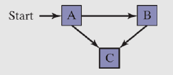
The above eaxmple is an example of a graph representing a FSM. The A node, being a start node is called initial state, and the C node is a terminal state - a point at which the program might stop without producing an error. The initial state is represented by an arrow coming into it, and terminal state has a thicker border around the square.
A FSM is a specific instance of a more general type of structure called a direct graph.
Validating an Input String
Programs reading input streams must validate their input by performing error checking. A compiler can use FSM to scan source programs, convert words and symbols into tokens, which are usually keywords, arithmetic operators, and identifiers.
When using FSM to check validity of input string, it's usually read character by character. Each input is represented by an edge (transition) in the diagram. A FSM detects illegal input in two ways:
- Next input character does not correspond to any transitions from the current state
- End of input is reached and current state is a nonterminal state
Character String Example
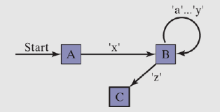
An example string validity based on following rules:
- The string ust begin with 'x' and and with 'z'
- Between the first and last characters, there can be 0 or more letters within range 'a'-'y'
The below diagram shows this FSM. Each transition is identified with a particular type of input. The transition from state A to B can be only accomplished if the letter 'x' is read from the input stream. The transition from B to C occurs only when 'z' is read.
Validating a Signed Integer
A FSM for parsing a signed integer is shown below. Input might have an optional leading sign, followed by sequence of digits.
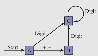
The complete implementation of this FSM in assembly might look as follows:
INCLUDE Irvine32.inc
ENTER_KEY = 13

.data
	InvalidInputMsg BYTE "Invalid input", 13, 10, 0
.code
main PROC
	call GetNext           ; read next char into AL
	cmp al, '+'
	je StateB
	cmp al, '-'
	je StateB
	call IsDigit           ; ZF = 1 if AL contains a digit
	jz StateC
	call DisplayErrorMsg
	jmp Quit

StateB:
	call GetNext
	call IsDigit
	jz StateC
	call DisplayErrorMsg
	jmp Quit

StateC:
	call GetNext
	call IsDigit
	jz StateC
	cmp al, ENTER_KEY
	je Quit
	call DisplayErrorMsg
	jmp Quit

Quit:
	call Crlf
	exit
main ENDP

GetNext PROC
	call ReadChar
	call WriteChar
	ret
GetNext ENDP

DisplayErrorMsg PROC
	push edx
	mov edx, OFFSET InvalidInputMsg
	call WriteString
	pop edx
	ret
DisplayErrorMsg ENDP
END main

===================================
====== IsDigit from Irvine32 ======
===================================
IsDigit PROC
	cmp al, '0'
	jb ID1
	cmp al, '9'
	ja ID1
	test ax, 0     ; al has a digit, so we guarantee ZF is set (AND with 0)
ID1: ret
IsDigit ENDP
Conditional Control Flow Directives
In 32-bit mode, MASM includes some high-level conditional control flow directives to help simplify coding of conditional statements.
They cannot be used in 64-bit mode.
Those directives are recognized by an assembler during preprocessing step, and translated into proper equivalent statements.
List of conditional control flow directives:
.BREAK- terminates.WHILEor.REPEATblock.CONTINUE- jump to top of.WHILEor.REPEATblock.ELSE- begins block of statements to execute whenIFis false.ELSEIF condition- another condition following failedIFcondition.ENDIF- terminates.IF,.ELSE, or.ELSEIFblocks.ENDW- terminates.WHILEblock.IF condition- generates block that executes when condition is true.REPEAT- generates block that repeats until condition becomes true.UNTIL condition- repeating block between.REPEATand.UNTIL.UNTILCXZ- repeats block between.REPEATand.UNTIL, until.WHILE- executes code between.WHILEand.ENDW, if condition = true
IF Statements
The .IF, .ELSE, .ELSEIF, .ENDIF directives make it very easy to code multiway branching logic. Assembler generates appropriate CMP and conditional jumps based on the conditions.
The condition is a boolean expression using the same operators used in C++ and Java (
Valid conditions:
Flag-based operators:
CARRY?- true if CF is setOVERFLOW?- true if OF is setPARITY?- true if PF is setSIGN?- true if SF is setZERO?- true if ZF is set
Loops using .REPEAT and .WHILE Statements
A .REPEAT-.UNTIL directives work in the same manner as do-while loop.
.REPEAT
	statements
.UNTIL condition
==================
mov eax, 0
.REPEAT
	inc eax
	call WriteDec
	call Crlf
.UNTIL eax == 10
The .WHILE-.ENDW corresponds to the classic while loop
.WHILE condition
	statements
.ENDW
===================
.WHILE eax < 10
	inc eax
	call WriteDec
	call Crlf
.ENDW